Performance Evaluation of New Rotary Blades and Roller Cutter of Versatile Multi-Crop Planter on Residue Management
Performance Evaluation of New Rotary Blades and Roller Cutter of Versatile Multi-Crop Planter on Residue Management
Abdullah Al Musabbir1, Md Abedur Rahman2*, Naveed Anjum2, 3 and Mustajab Ali4,5
(A) VMP with blades (B) Roller cutter during trials.
Engineering (2D) view of roller cutter; (A) Front view, (B) side view and (C) cross sectional view of A-A section, and (D) photographic view of roller cutter.
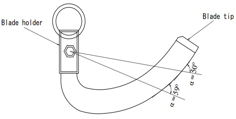
Cutting angle of time and changes of α with increasing of θ.
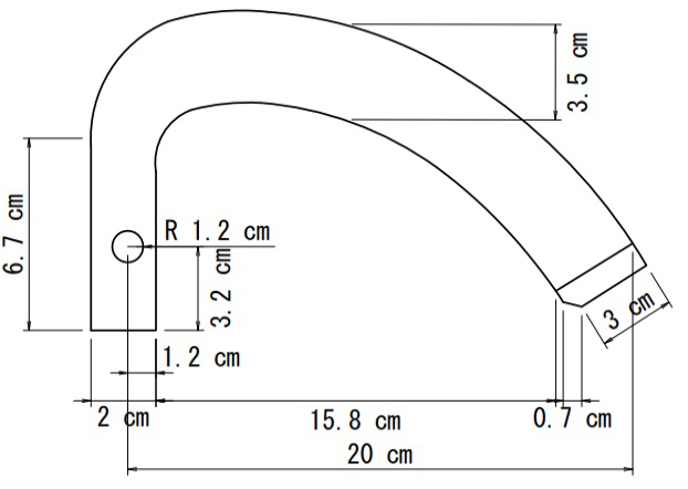
Engineering view of new rotary blade with measurement of tip angle is 45°
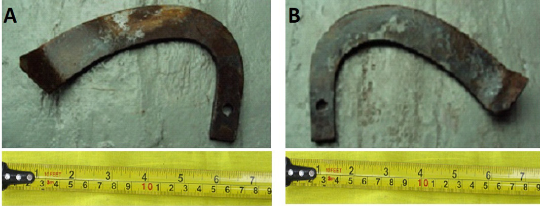
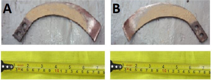
Rotary Blade B (A) Tip angle left, and (B) Tip angle right.
Blade Arrangement of planter (A) ST mode, (B) ZT mode.
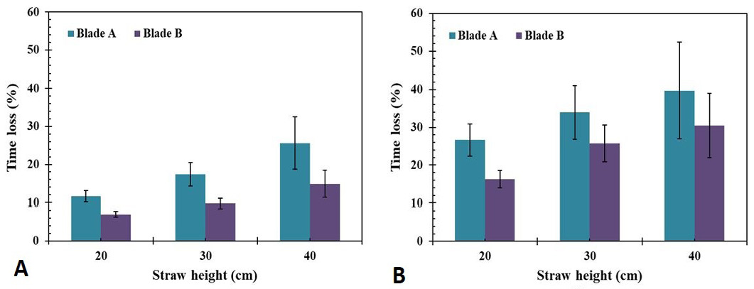
Time loss by both types of blades in ST system (A) anchored straw (B) loose straw.
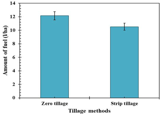
Rate of fuel consumption in different tillage methods.
Strips made by (A) Blade A, and (B) Blade B.
Rotary Blade A (A) Tip angle left, and (B) Tip angle right.
Effective Field Capacity by two types of blades (A) anchored straw (B) loose straw.
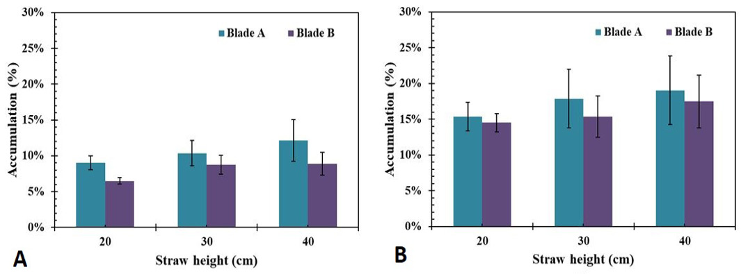
Straw accumulations by two types of blades (A) anchored straw (B) loose straw.


