Development of Electrostatic Particulate Collection System for Agricultural Biomass Based Energy Applications


Research Article
Development of Electrostatic Particulate Collection System for Agricultural Biomass Based Energy Applications
Imad Hassan1, Bilal-ur-Rehman2, Muhammad Amir2, Faheem Ali2*, Salman Ilahi2 and Amjad Ali3
1Ghandhara Institute of Science and Technology, Peshawar, Khyber Pakhtunkhwa, Pakistan; 2University of Engineering and Technology, Peshawar, Khyber Pakhtunkhwa, Pakistan; 3Sarhad University of Science and Technology, Peshawar, Khyber Pakhtunkhwa, Pakistan.
Abstract | The use of agricultural based biomass through combustion is playing an important role in the production of heat and electricity worldwide. The emission of particulate matter pollution from biomass combustion has drawn significant attention because of its harmful effects on human health and environment. Consequently, it becomes important to have a simple and cost effective solution to avoid the problems of air pollution due to the combustion of biomass. Using an Electrostatic Precipitator (ESP) is an effective method for the removal of particulate matter from industrial processes and boilers. This research proposes the development of a cost effective, simple and compact ESP, through practical installation and efficiency analysis. Experimental evaluation of the proposed ESP design is carried out for the removal of particulate matter from a biomass combustor. The results shown in this paper are promising and exhibit that a simple solution can achieve above 90% efficiency. The average particulate collection efficiency of our proposed ESP reached its peak stable value of 99.1% when tested with applied voltage of 25kV at an air velocity of 0.5 m/s. Moreover, it was observed and shown in this paper that when the voltage was increased beyond 25kV, the efficiency of the design lost its stability due to back corona effect. The filtration system proposed in this paper shows the ability of an efficient tool for controlling the flow of particulate pollutant matter from biomass combustion under particular conditions.
Received | June 16, 2019; Accepted | June 16, 2020; Published | July 22, 2020
*Correspondence | Faheem Ali, University of Engineering and Technology, Peshawar, Khyber Pakhtunkhwa, Pakistan; Email: faheem@uetpeshawar.edu.pk
Citation | Hassan, I., B. Rehman, M. Amir, F. Ali, S. Ilahi and A. Ali. 2020. Development of electrostatic particulate collection system for agricultural biomass based energy applications. Sarhad Journal of Agriculture, 36(3): 742-747.
DOI | https://dx.doi.org/10.17582/journal.sja/2020/36.3.742.747
Keywords | Biomass, Electrostatic precipitator, Particulate, Emissions, Combustion
Introduction
Climate change has brought added pressure for using renewable energy resources for producing heat and electricity. Worldwide, the use of biomass is considered to be a sustainable source of energy. However devices that use wood as a fuel are a leading cause of air pollution. Therefore, awareness is required for the protection of the environment without causing any hindrance to the development of the society by making an effort for a considerable reduction of pollution from industrial applications. That is why it is now very important to acquaint mandatory scientific knowledge for the advancement of this sustainable development (Atika et al., 2019; Faisal et al., 2019; Bologa et al., 2009; Nussbaumer, 2003; Reynolds et al., 1976).
The emission of particulate matter in the outer atmosphere is a matter of great concern. Human health is negatively affected by these fine particles and these particles are especially dangerous for children. The emissions of small particles to the outer atmosphere are directly responsible for different types of diseases such as bronchitis and asthma. In some areas these fine particles are also responsible for the decrease in life expectancy. Therefore, controlling the emission of such fine particles in the atmosphere is essential. The construction of a simple, reliable, cost effective and efficient ESP is a feasible solution to this problem. It offers a number of advantages, including its high efficiency even for submicron particles, low operating and maintenance cost and its ability to operate in extreme conditions makes its use ideal for controlling air pollution in many industries (Atika et al., 2019; Bologa et al., 2009; Kocik et al., 2005).
In the past different bodies responsible for the control of air pollution in the atmosphere authorized the operation of ESPs at comparatively low collection efficiencies. However, after changes in the procedure, it is now essential for ESPs to have efficiencies greater than 90% for controlling certain particulate matter. ESPs can be designed to meet the new regulations. However, innovative solutions are required for reduction of the size and cost of the precipitators (Bologa et al., 2009; Kocik et al., 2005).
For the designing of an efficient collection system for biomass combustion, the important factors to be considered are the maintenance, cost of the design material, high operating temperature and the dimensions of the system. ESPs operate on the principle of electrostatic forces. The size of small particles emitted during the combustion of biomass ranges from 0.1 µm - 100 µm (µ - micro) in diameter. ESPs are very effective for the removal of fine particles having a diameter less than 10 µm that is why it is one of the most efficient devices for the collection of fine particles in appliances that use wood as a fuel (Chenghang et al., 2017; Ruttanachot et al., 2011; Lin and Tsai, 2010; Intra et al., 2010; Falaguasta et al., 2008).
Materials and Methods
Design of ESP
The main performance requirements of the ESP are defined by the concentration of the mass of fine particles and their size range. Generally, an ESP must have very low maintenance requirements and should be safe to operate (Thomas et al., 2014; Lin et al., 2012; Hoenig, 1981). Figure 1 shows the practical schematic sketch of the ESP used in this research. It has four major parts as:
- The particulate collection tube.
- The gas inlet tube.
- The gas outlet tube.
- A high voltage power supply.
Collector
A schematic diagram of particulate collector is shown in Figure 1. The dimension of this particulate collector shows that the diameter of the discharge electrode is 5mm and the height of the discharge electrode is 200mm. Stainless steel rods were used for the making of discharge electrodes .The collection plate is also made of steel and the height of the collection plate is 300mm with a width of 288mm as shown in Table 1.
|
Dimensions |
Values |
|
Number of electrodes |
2 |
|
Height of discharge electrode |
200mm |
|
Diameter of discharge electrode |
5mm |
|
Height of collection plate |
300mm |
|
Width of collection plate |
288mm |
|
Distance b/w discharge electrode and collection plate |
150mm |
|
Applied voltage on discharge electrode |
10kv-25kv |
Negative high voltage is supplied to the corona discharge electrode and the collection plate is grounded. A corona discharge field is created between the discharge electrode and the collection plate due to the high voltage power supply. A small fan is used to propel the air inside the collector. The flow of the exhaust gas laden by the particulate matter moves across the discharge field. A negatively charged deflector is installed in the collector and is used to repel the charged particles in an outward direction towards the collection plate. The collisions of ions with the particles produced the charge on the particles inside the ESP. The transportation of ions takes place due to the electric field. The sampling flow is controlled by a flow controller. The size of the particulate matter is in the range of 0.1µm to 10µm. All the tests in the lab were conducted under stable ambient conditions.
The charged particles were then moved in an outward direction and the fine particles were collected in the wall of the collection plate. The collection efficiency of the ESP, as shown through Equation 1 is obtained as the ratio of the difference between the concentration of the particles at the outlet and inlet to the concentration of the particles at the inlet (Kocik et al., 2005). It is assumed that the particles were distributed uniformly throughout the particulate collector.
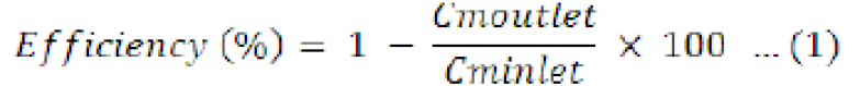
Where; Cmoutlet and Cminlet are the concentration of the mass of the particles at the outlet and inlet respectively.
Electric field intensity
The strength of the electric field is a critical factor in the performance of the ESP as it generates corona for charging of the particles. The electric field is formed by the high potential applied to the discharge electrodes. The electric field E (Theraja, 2007) can be calculated using the relation given as:
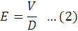
Where; V represents the applied potential and D represents the separating distance between the discharge electrode and the collection electrode (Thomas et al., 2014; Lin et al., 2012).
Table 2 shows that with an increase of the applied potential, the strength of the electric field in the ESP increased. Consequently, the particle collection efficiency, increased with the increase in the electric field strength due to high charging of the particles.
Power supply
The DC power supply for the generation of electric field strength inside the ESP is of our particular interest as it can generate not only the field strength but also ion concentration which increases the charging of the particles due to the ions greater electrical mobility (Thomas et al., 2014; Lin et al., 2012; Hoenig, 1981). This improves the collection efficiency of fine particles. For the generation of a very strong electric field between the discharge electrodes and collecting plates a high voltage power supply is used. In this implementation, a high voltage static generator is used for the supply of high voltage output. The high voltage supply is adjustable up to 50kV and the constant current is adjustable between 0µA and 260µA. A digital 7-segment display is used to show the selected output voltage or current.
Table 2: Calculation of the electric field strength.
|
D(m) |
0.0725 |
||||||
|
Voltage (kv) |
10 |
15 |
20 |
25 |
|||
|
Electric field intensity (kv/m) |
138 |
207 |
271 |
345 |
|||
|
Efficiency (%) |
|||||||
|
V= 0.5 m/s |
95.5 |
96.2 |
98.4 |
99.1 |
|||
Results and Discussion
The variation of the collection efficiency with different corona voltages at a given air velocity is shown in Table 3. The calculated data are collected for particle the size of 0.1µm. The concentration of the mass of the particles at the ESP upstream is 12 - 40 mg/Nm3 and in clean air is 0.6 - 20 mg/Nm3.
Table 3: Collection efficiency with different Voltages.
|
Voltage (kV) |
Air velocity (m/s) |
Avg efficiency (%) |
|
10 |
0.5 |
95.7 |
|
15 |
0.5 |
96.4 |
|
20 |
0.5 |
98.4 |
|
25 |
0.5 |
99.1 |
|
10 |
0.8 |
95.4 |
|
15 |
0.8 |
96.2 |
|
20 |
0.8 |
98.3 |
|
25 |
0.8 |
99 |
|
10 |
1.5 |
95 |
|
15 |
1.5 |
95.9 |
|
20 |
1.5 |
98.1 |
|
25 |
1.5 |
98.9 |
|
10 |
1.8 |
94.75 |
|
15 |
1.8 |
95.8 |
|
20 |
1.8 |
97.5 |
|
25 |
1.8 |
98.8 |
Comparison of the collection efficiencies of our proposed ESP is shown in Figure 2. The efficiency is plotted against varying applied voltage and air velocity. The voltage is changed from 10kV to 25kV while the air velocity varies between 0.5m/s and 1.8m/s.
Table 4: Collection efficiency with different air velocities.
|
Voltage (kV) |
Air velocity (m/s) |
Avg efficiency (%) |
|
10 |
0.5 |
95.7 |
|
10 |
0.8 |
95.4 |
|
10 |
1.5 |
95 |
|
10 |
1.8 |
94.75 |
|
15 |
0.5 |
96.4 |
|
15 |
0.8 |
96.2 |
|
15 |
1.5 |
95.9 |
|
15 |
1.8 |
95.8 |
|
20 |
0.5 |
98.4 |
|
20 |
0.8 |
98.3 |
|
20 |
1.5 |
98.1 |
|
20 |
1.8 |
97.5 |
|
25 |
0.5 |
99.1 |
|
25 |
0.8 |
99 |
|
25 |
1.5 |
98.9 |
|
25 |
1.8 |
98.8 |
For a given constant air velocity of 0.5 m/s the voltage is changed from 10kV to 25kV. The increase in the applied voltage showed that the collection efficiency of the ESP increased. The increase in applied voltage resulted in an increase in the electric field strength of the ESP due to which the particle charging increased and hence resulted in an increase in the collection efficiency of the ESP. The highest efficiency is obtained when the applied voltage is set at 25kV and the air velocity is 0.5m/s. During the experiment, it is also found out that when the applied potential is increased to its maximum value, the collection efficiency of the ESP increased proportionally. However, after this point the decrease in collection efficiency is observed due to the onset of back corona. As a result of which, the spark over voltage is reduced. The collection efficiency is also plotted for a constant applied voltage and by varying the air velocity as shown in Table 4.
Figure 3 shows that the efficiency decreased with the increase in the air velocity. Air velocity is one of the most important of all factors that affected the collection efficiency of the ESP. Inside the ESP the air velocity is used to control the retention time of the particle. Increasing the air velocity decreased the retention time which lead to a decrease in the collection efficiency of the ESP. Cleaning of the plate also affected the collection efficiency, the higher collection efficiency could not be maintained after the deposition of tar on the collection electrode after combustion as it resulted in reduced electric field strength. Therefore, proper cleaning of the system is deemed important for effective removal of the fine particles.
Currently, the proposed prototype is compact; therefore its use is only suggested for domestic purposes and in small scale industries. It should be duly noted that the efficiency of the proposed ESP is not suitably stable for higher voltages therefore it must not be operated with voltages higher than 25kV. The fundamental reason for such instability beyond 25kV in the proposed design is the onset of back corona effect produced by the particulate collection plate (same as in high voltage transmission lines resulting in line-losses) (Faisal et al., 2019; Chenghang et al., 2017; Theraja, 2007). The varying back corona effect causes fluctuation of the spark over voltage (Theraja, 2007) consequently inducing instability in the collection process as shown in Figure 2.
Conclusions and Recommendations
Through this research, a simple and small scale ESP for the removal of fine particles from agricultural biomass combustion is designed, installed, operated and investigated. Some of the factors that affected the collection efficiency of the ESP were evaluated. The overall efficiency is demonstrated to be above 90%. It is found that the efficiency is positively affected by the increase in the applied voltage and the strength of the electric field and the collection efficiency is found to be decreasing with the increase in air velocity. The installation and operation of the ESP are seen as compatible to the biomass fired furnace. The design of the proposed ESP is not complex with almost any implementation glitches. The proposed ESP can be operated for several hours continuously for the effective removal of fine particles. Moreover, continued maintenance of the collector is recommended for smooth operation and high collection efficiency.
Acknowledgements
The authors would like to thank all the learned colleagues of the affiliated institutions for their selfless expert input and technical facilitation.
Novelty Statement
The design proposed in this manuscript provides a simplest solution for biomass based energy production applications with an efficiency above 90%. Considering the economic condition of Pakistan, small scale cottage industries and irrigation applications in agricultural domain can benefit from this cost effective simple arrangement.
Author’s Contributions
The practical design described in the manuscript is proposed by Imad Hassan and is implemented in collaboration with Bilal-ur-Rehman. Physical-viability-verification of the proposed design is done by Muhammad Amir. Faheem Ali carried out the statistical analysis on the collected data sets. Drafting of the manuscript was done by Salman Ilahi while final proof reading was carried out by Amjad Ali. All authors read and approved the final manuscript.
Conflict of interest
The authors have declared no conflict of interest.
References
Atika, Q., F. Hussain, N.A. Rahim, G. Hardaker, D. Alghazzawi, K. Shaban and K. Haruna. 2019. Towards sustainable energy: A systematic review of renewable energy sources, technologies and public opinions. IEEE Access. 7: 63837-63851. https://doi.org/10.1109/ACCESS.2019.2906402
Bologa, A., H.R. Paur, H. Seifert and K. Woletz. 2009. Particle collection by an electrostatic precipitator from the exhaust gas of a wood combustion stove. 4th Eur. Comb. Meet., 14-17 April, Vienna, Austria. paper No. 810026.
Chenghang, Z., Z. Shen, Q. Chang, Q. Su, X. Zu and X. Gao. 2017. Experimental study on electrostatic precipitation of low-resistivity high-carbon fly ash at high temprature. Energy Fuels. https://doi.org/10.1021/acs.energyfuels.7b00107
Faisal, R.B., P. Das, S.K. Sarker and S.K. Das. 2019. A survey on control issues in renewable energy integration and microgrid. Prot. Contr. Mod. Power Syst.
Falaguasta, M.C.R., J. Steffens, E.E. Valdes and J.R. Coury. 2008. Overall collection efficiency of a plate wire electrostatic precipitator operating on the removal of PM2.5. 38: 179-186.
Hoenig, S.A., 1981. New application of electrostatic technology to control dust, fumes, smokes and aerosols. IEEE Trans. Ind. Appl. 17: 386-391. https://doi.org/10.1109/TIA.1981.4503964
Intra, P., P. Limueadphai and N. Tippayawong. 2010. Particulate emission reduction from biomass burning in small combustion systems with a multiple tubular electrostatic precipitator. Part. Sci. Technol. 28(6): 547-565. https://doi.org/10.1080/02726351003758444
Kocik, M., J. Dekowski and J. Mizeraczyk. 2005. Particle precipitation efficiency in an electrostatic precipitator. J. Electrostat. 63: 761-766. https://doi.org/10.1016/j.elstat.2005.03.041
Lin, G.Y. and C.J. Tsai. 2010. Numerical modeling of nanoparticle collection efficiency of single-stage wire-in-plate electrostatic precipitators. Aerosol Sci. Technol. 44: 1122-1130. https://doi.org/10.1080/02786826.2010.512320
Lin, G.Y., T.M. Chen and C.J. Tsai. 2012. A modified Deutsch-Anderson equation for predicting nanoparticle efficiency by electrostatic precipitators. Aerosol Air Qual. Res. 12: 697-706. https://doi.org/10.4209/aaqr.2012.04.0085
Nussbaumer, T., 2003. Combustion and co-combustion of Biomass: Fundamentals, Technologies, and Primary Measures for Emission Reduction. Energy Fuels. 17 (6): 1510-1521. https://doi.org/10.1021/ef030031q
Reynolds, J.P., L. Theodore and J. Marino. 1976. Calculating collection efficiencies for electrostatic precipitators. J. Air Pollut. Contr. Assoc. 25 (6): 610-616. https://doi.org/10.1080/00022470.1975.10470116
Ruttanachot, C., Y. Tirawanichakul and P. Tekasakul. 2011. Application of electrostatic precipitator in collection of smoke aerosol particles from wood combustion. Aerosol Air Qual. Res. 11: 90-98. https://doi.org/10.4209/aaqr.2010.08.0068
Theraja, B.L., 2007. A textbook of electrical technology. Volume 3. S. Chand Publishers Limited, Ghazabad, India.
Thomas, F., N. Grab, N. Zouzou, L. Dascalescu, R. Greil and N. Hopf. 2014. Smart home precipitator for biomass furnaces: Design considerations on a small-scale elctrostatic precipitator. IEEE Trans. Ind. Appl. 50: 2219-2224. https://doi.org/10.1109/TIA.2013.2288430
To share on other social networks, click on any share button. What are these?