
Advances in Animal and Veterinary Sciences


Review Article
Advances in Animal and Veterinary Sciences. 1 (2S): 33 – 36Special Issue–2 (Clinical Veterinary Practice–T rends)
AO techniques of Dynamic Compression Plate (DCP) and Limited Contact Dynamic Compression Plate (LC–DCP) Application for Fracture Management in Dogs
Subburamanujam Ayyappan
-
Department of Clinics, Madras Veterinary College, Chennai, India
*Corresponding author:jujups61@hotmail.com
ARTICLE CITATION:
Ayyappan S (2013). AO techniques of dynamic compression plate (DCP) and limited contact dynamic compression plate (LC–DCP) application for fracture management in dogs. Adv. Anim. Vet. Sci. 1 (2S): 33 – 36.
Received: 2013–11–31, Revised: 2013–12–30, Accepted: 2013–12–31
The electronic version of this article is the complete one and can be found online at
(
http://nexusacademicpublishers.com/table_contents_detail/4/215/html
)
which permits unrestricted use, distribution, and reproduction in any medium, provided the original work is properly cited
ABSTRACT
The AO group developed techniques and implants for fracture management initially in human beings in the 1950’s and these were later extrapolated for use in veterinary patients in the late 1970’s. Dynamic compression plates and limited contact dynamic compression plates have become increasingly popular in human orthopaedic surgery and gradually gained popularity in veterinary orthopaedics during recent past. The present review describes the principles, application techniques and relative advantages and disadvantages of two techniques of bone plating in veterinary orthopaedic patients.
INTRODUCTION
The aim of fracture management is to anatomically reconstruct the fractured limb and restore ambulation of the affected limb as early as possible. The dynamic compression plate (DCP) is a special plate developed by the AO group (Perren et. al.,1969) specifically to bring about axial compression and stabilization of simple transverse fractures by countering rotational, bending and shear forces thus promoting primary healing and early return to function. The technique of application is based on the configuration of fractures and can be used to perform functions of compression, neutralisation or a buttressing (Prieur, 1983). Brinker and associates (1977) summarized guidelines for plate selection based on the type of bone involved and body weight of the animal. Normal functional usage of the limb was reported when compression plating was performed to stabilise long bone fractures (Braden and Brinker, 1973). The Limited Contact Dynamic Compression Plate (LC–DCP) was the second generation plate developed by the AO group (Perren et. al., 1990). The concept of using these two plates is identical. The differences between the plates include a different shape such that there is less contact with the bone and the underside of the LC–DCP ("low contact”) hence promoting increased cortical perfusion.
The Principle of Compression
In this application principle, the plate is applied to the bone under tension, which in turn compresses the bone fragments bridged by the plate. The geometry of the oval hole of the DCP and the LC–DCP allows these plates to be used as self–compressing plates. The oval shape of the DCP hole is designed to generate compression at the fracture site. Each screw hole has an eccentrically placed ‘slope’ directed towards the center of the plate and is referred to as the eccentric hole. Eccentric placement of a fully threaded cortical screw in the ‘slope’ generates 1mm of compression towards the fracture site. The plate and bone will move longitudinally towards each other, the bone will be subjected to compression and the plate will come under tension. The DCP or LC–DCP can be applied as a compression plate in transverse or short oblique fractures of the diaphysis. It can be used to generate both static and dynamic compression at the fracture site.
The DCP or LC–DCP comes in different sizes. The DCP 4.5 is used with 4.5 mm cortex screws, 4.5 mm shaft screws. The DCP 3.5 is used with 3.5 mm cortex screws, and the DCP 2.7 is used with 2.7 mm cortex screws, while the DCP 2.0 is used with 2.0 mm cortex screws (Koch, 2005). The DCP or LC–DCP 4.5 is used for long bone fracture management in large and giant breed dogs. The DCP or LC–DCP 3.5 is used for fracture management in medium to large dogs. The DCP or LC–DCP 2.7 is used for fracture management in small to medium sized dogs and large cats and DCP 2.0 is used for fracture management in cats and toy breed dogs. The plates perform the function of neutralization (protects the interfragmentary compression achieved by lag screw as in fractures with ‘butterfly fragments’), compression (simple unstable ‘two piece’ fractures) or as buttress or bridging plate (prevents fracture collapse in non–reducible comminuted fractures) (Schatzer, 1991).
Static Compression
This is interfragmentary compression generated at the time of surgery, and it remains relatively constant and only diminishes with normal healing and remodelling of the bone. If implant failure occurs, such as screw loosening, there would be immediate loss of compression. Interfragmentary compression does not result in faster, better or stronger healing. All it does is increasing friction at the fracture site, between the fragments, which increases stability of the bone–implant composite. The three methods of generating static compression are as follows:
Tensioning Device
This can only be used with a 4.5 DCP. It is attached to the end of the plate, and so needs a longer incision and about 3–4 cm more bone. It is rarely used in dogs and simple fractures are still best reduced and stabilized by use of "classical” DCP using load screws. However, when needed, the tension device can compress a fracture site by up to 2 cm, and is useful for compressing soft tissues within the gap in non unions.
Load Screws
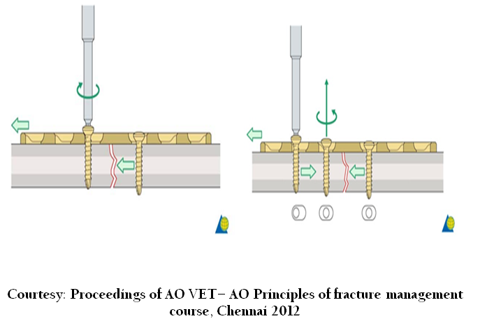
Insertion of screws in the load position, using the yellow load guide is the most common method of obtaining static compression with a DCP. Holes in the DCP are oval shaped, and have a glide path for the screw head. Use of the load guide permits a hole to be drilled at the end of this oval hole. When the screw is placed and tightened in the eccentric hole, the screw head binds on the glide path in the plate hole, and moves the bone towards the fracture. Provided that the fracture has been anatomically reduced, this will cause interfragmentary compression. Up to two screws on each side of the fracture can be inserted in the load position.
The Screw Head, like a Ball, Slides down Inclined Plane
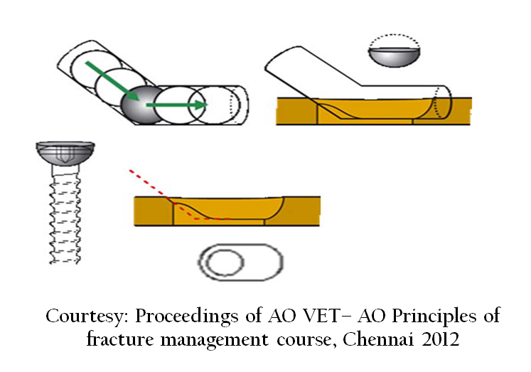
Below, Neutral guide (green), which centers the screw in the hole of the plate; Right, Load guide (yellow), which eccentrically places the screw in the hole of the plate (this eccentric position is furthest away from the fracture –note position of arrow on the guide). The latter position results in the screw moving towards the fracture as the screw head contacts the plate.
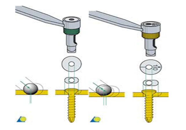
The same functions, neutral and load, can be performed with the universal drill guide. Left, neutral position where the inner spring–loaded cylinder is completely depressed such that the outer cylinder rests completely within the screw hole of the plate, which centers the screw in the hole of the plate; Right, load position where the inner cylinder remains in the extended position, and it is placed adjacent to the edge of the screw hole in the plate (furthest away from the fracture), which eccentrically places the screw in the hole of the plate. The latter position results in the screw moving towards the fracture as the screw head contacts the plate (See figure below).
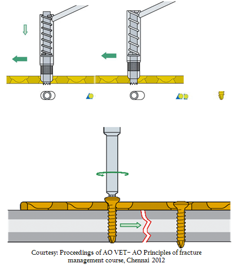
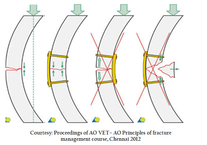
Plate application on the tension surface of bone causes interfragmentary compression (above figure) as the animal bears weight on the limb, and so this is cyclic in nature. On the femur, for example, the tension surface is lateral, and because the bone is loaded eccentrically, the fracture site tends to "close" (dynamic compression), and correspondingly the plate will be in tension (See below figure)
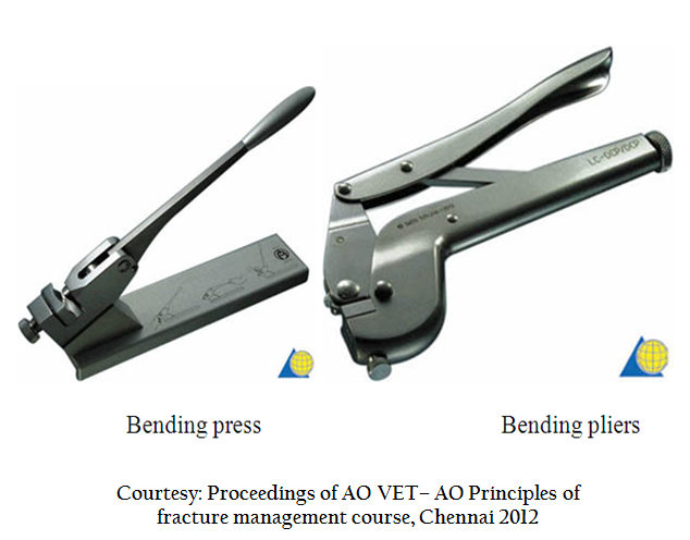
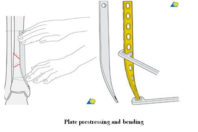
The appropriate plate size must be selected. As a guide, the width of the plate should be approximately 75% of the bone diameter. Broader or stiffer plates are needed for plates with buttress or bridging function. The length of the plate should be sufficient to have at least three screws (6 cortices) in the bone fragments on either side of the fracture (in un–fractured bone – NOT crossing any fracture lines). Longer plates are needed in osteoporotic bone or soft bone (young animals), and in larger or more active animals where greater loading is anticipated; a general rule is to plate the majority of the length of the bone. Plates must be prestressed to fit the surface of the bone. The greater the bone–plate contact, the greater the stability imparted to the reduction and fixation. If the plate is improperly contoured, loss of reduction may occur as the screws are tightened. This is especially important in cases of intra–articular fractures (e.g., in the acetabulum). Another important principle in contouring is the concept of "pre–stressing" the plate, especially with compression plate application. When plates are contoured to closely correspond to the bony surface, and placed under tension, the result is asymmetric compression of the bone fragments and only a small area (<20%) of the bone in contact at the fracture line. The fracture line immediately under the plate (cis cortex) is compressed; however, the fracture line at the opposite (trans) cortex will gap open. This limited contact results in the plate supporting all the applied loads without any significant contribution of bony support. Numerous studies have demonstrated that this gap at the trans cortex can be eliminated, thereby increasing fracture stability, by pre–stressing the plate. Pre–stressing is performed by slightly over–bending the plate such that a small gap of 1.0 – 2.0 mm is present between the bone and the plate at the fracture line. Compression of the trans cortex, in addition to the cis cortex, thus is obtained. Plate contouring is performed using either hand held bending pliers or a plate bending press. Bending irons also are used in order to twist the plate around its longitudinal axis. Plates should be bent and/or twisted in gentle curves, as abrupt changes in direction do not properly mirror the bony surface and result in poor bone–plate contact. If possible, the plate should be bent between – and not at – the screw holes. Plastic deformations associated with plate contouring applied in this manner on a one–time only basis are not detrimental to the plate (metal fatigue) and do not result in decrease of strength of the implant.
Compression Plate Application
Plate positioned and secured on the first fragment; a drill hole is placed through the eccentric drill guide in the second fragment. Tightening of the screw in the eccentric drill hole causes movement of the bone relative to the plate (1.0 mm) thus promoting compression of the two fracture fragments. The remaining screws are placed in the bone using the neutral guide (See below figure)
DCP vs. LC–DCP
The LC–DCP is the second generation plate developed by the AO group (Perren et. al., 1990). The concept of using these two plates is identical. The differences between the plates include a different shape such that there is less contact with the bone and the underside of the plate (low contact) hence promoting increased cortical perfusion.
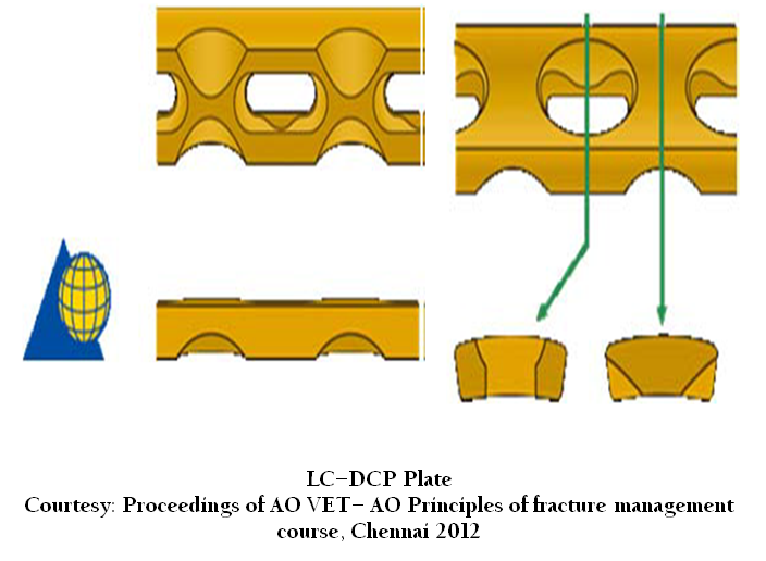
LC-DCP Plate Courtesy: Proceedings of AO VET– AO Principles of fracture management course, Chennai 2012
These "cut–outs” also permit more uniform plate bending ( Bourdrieau,2011), as there no longer is a stress riser at the level of the screw hole. The screw holes have uniform spacing (rather than the spacer section in the center of the DCP), which allows easier positioning on a plate over a fracture line, especially in the metaphyseal bone ends. These holes are spaced slightly wider apart than those in the DCP (in order to accept the "cut–outs” and maintain uniform bending stiffness) and the LC–DCP was less stiff and stronger than the DCP (Little et. al., 2001). In addition, there are undercuts on the under surface of the longitudinal ends of the plate holes that permit greater angling of the screws in this plane (80° with the LC–DCP as compared to 50° with the DCP) (Perren, 1991). Lastly, these screw holes have symmetric holes, thus the basic spherical gliding principle present at both sides of the hole (vs. the asymmetric shape and the inclined plane present at only the far side of the hole with the DCP); this allows compression to be applied with the screw in either direction, which allows greater versatility in plate/screw application. The LC–DCP is slightly different, and not interchangeable. The universal guide simplifies the instrumentation in that it can be used interchangeably between either plate types.
Conventional plates such as the DCP and LC–DCP may continue to be the fixation method of choice for periarticular fractures which demand perfect anatomical reduction and to certain types of non unions which require increased stability for union (Igna and Schuszler, 2010).
REFERENCES
Brinker WD, Flo GL, Lammerding JJ and Bloomberg MS (1977). Guideline for selecting proper implant size for treatment of fractures in the dog and cat. J. Am. Anim. Hosp. Assoc. 13: 476–477.
Igna C and Schuszler L (2010). Current concepts of internal plate fixation of fractures. Vet. Med. 67: 118–124.
Koch D (2005). Implants: description and application. Screws and plates. In: AO Principles of Fracture Management in the Dog and Cat, Johnson AL, Houlton JEF, Vannini R (Eds.). George Thieme Verlag, Stuttgart. 27–51.
Little FM, Hill, CM, Kageyama T, Conzemius MG and Smith GK (2001). Bending properties of stainless steel dynamic compression plates and limited contact dynamic compression plates. Vet. Comp. Orthop. Traumatol. 14: 64.
Perren SM, Russenberger M, Steinemann S, Muller ME and Allgower M (1969). A dynamic compression plate. Acta Orthop. Scand. (Suppl) 125: 31–41.
Perren SM, Klaue K, Pohler O, Predieri M, Steinemann and Gautier E (1990). The limited contact dynamic compression plate (LC–DCP). Acta Orthop. Trauma. Surg .109: 304–310.
http://dx.doi.org/10.1007/BF00636166
Perren SM (1991). The concept of biological plating using the limited contact dynamic compression plate (LC–DCP). Scientific background, design and application. Injury 22 (Suppl 1): 1–41.
http://dx.doi.org/10.1016/0020-1383(91)90123-V
Braden TD and Brinker WD (1973). Effect of certain internal fixation devices on functional limb usage in dogs. J. Am.Vet. Med. Assoc. 162: 642–646.
PMid:4697362
Schatzer J (1991). Screws and Plates and their applications. In: Allgower M (Ed): Manual of internal fixation techniques recommended by the AO–ASIF group, 3rd edn, Springer Verlag. 179–199.
http://dx.doi.org/10.1007/978-3-662-02695-3_3
Prieur WD (1983). Plate classification according to function. In: Manual of Internal fixation of Small animals (Ed.) Brinker WO, Hohn RB and Prieur WO. Springer–Verlag, Berlin. 63–79. Boudrieau RJ (2011). Advances in managing long bone fractures. (Proceedings), In CVC group veterinary conventions.Washington DC, 2011