
In this research article, design of a beam steerable and frequency reconfigurable antenna for 5G communication system using three 1×8 element antenna arrays with defected ground structure has been presented. Frequency reconfigurability has been achieved by placing two switches inside an etched slot on patch antenna, which resulted in a matched bandwidth of 5.29 GHz (24.13 to 29.42 GHz). Beam steering has been achieved by placing the proposed antenna array along three different edges of a mobile phone and energizing only one array at a given time. The proposed antenna array has increased maximum directivity up to 14 dB and maximum gain up to 13 dB. Furthermore, by incorporating a defected ground structure (DGS), mutual coupling between the two adjacent elements has also been reduced up to 15%. The proposed antenna array can be a prospective candidate for 5G mobile handsets.
Research Article · Volume 39, Issue 1, 13 February 2021 · Open Access
Beam Steerable and Frequency Reconfigurable Antenna Array for 5G Mobile Networks
· ·
Affiliations & Notes ⌄
- 1Department of Electrical Engineering, University of Engineering and Technology, Peshawar, Khyber Pakhtunkhwa, Pakistan. *Correspondence: Shahid Bashir, Department of Electrical Engineering, University of Engineering and Technology, Peshawar, Khyber Pakhtunkhwa, Pakistan
- 2Email: shahid.bashir@uetpeshawar.edu.pk
Article Info ⌄
- Journal:
- Journal of Engineering and Applied Sciences
- Published:
- 13 February 2021

Abstract
The full text of this article is available as a PDF — use Download PDF above.
Figures

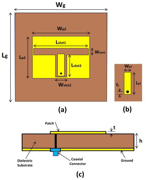
Proposed Antenna element. (a) Front view of antenna element (b) Inner patch of antenna element (c) Side view of antenna element.
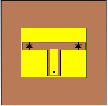
Antenna element with switches.

1x8 element array.
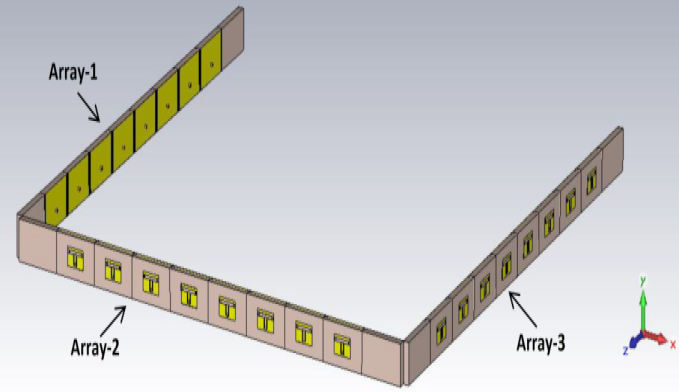
Proposed beam steering antenna array.
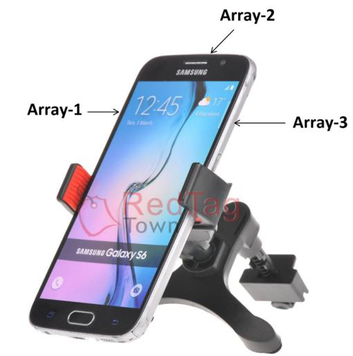
Prospective position of proposed array in typical mobile phone.
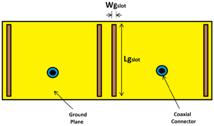
DGS at the ground plane between two elements.
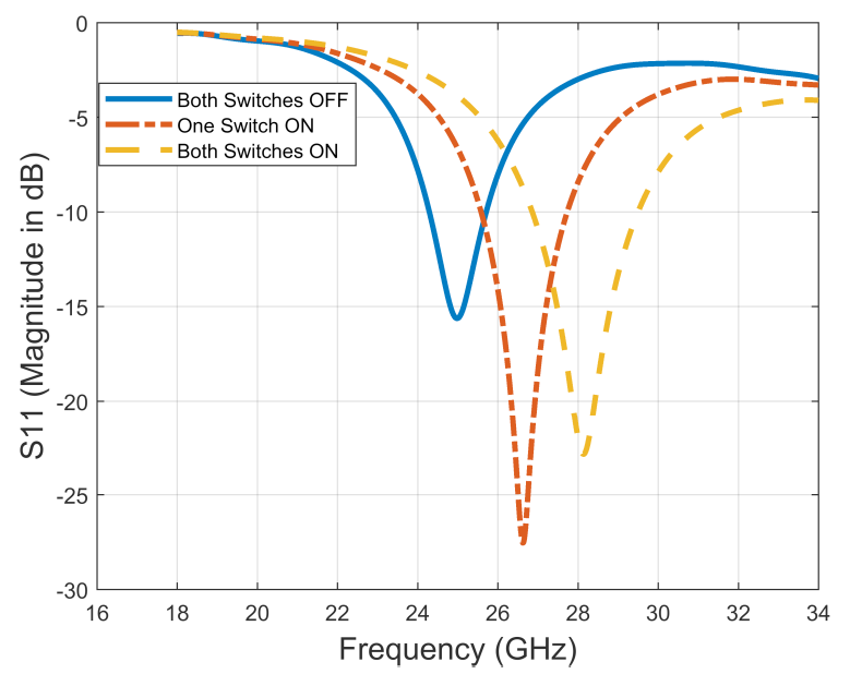
Return loss of single element.
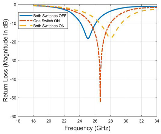
Return loss for the proposed antenna.
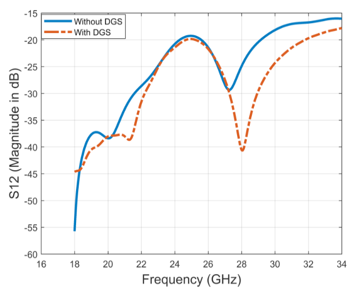
Mutual coupling between two elements by turning OFF both switches.
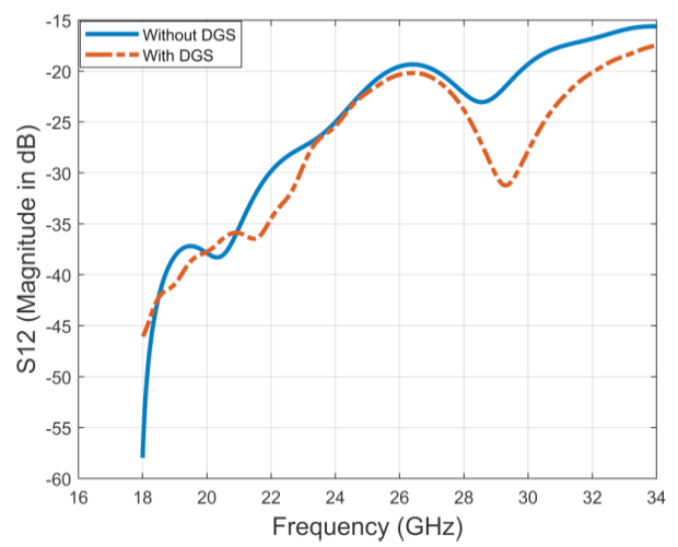
Mutual coupling between two elements by turning one switch OFF and one ON.
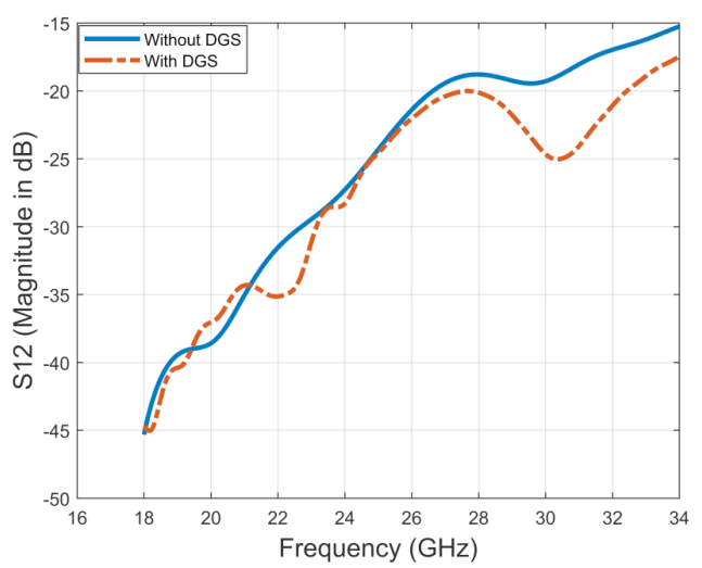
Mutual coupling between two elements by turning ON both switches.
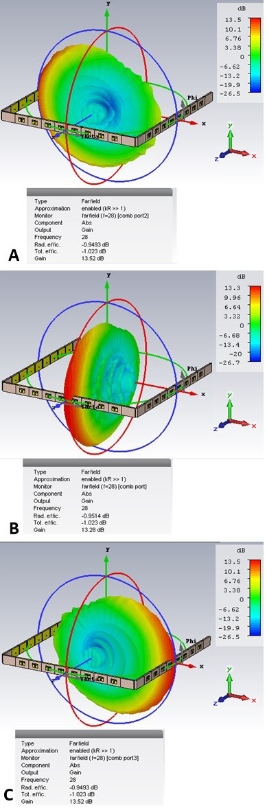
Simulated Radiation pattern; (a) Only Array-1 excited; (b) Only Array-2 excited; (c) Only Array-3 excited.
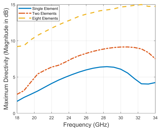
Maximum Gain vs Frequency.
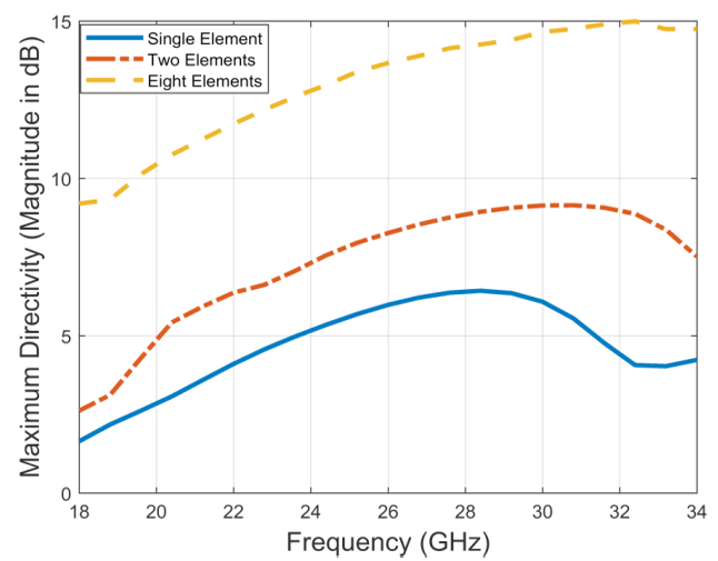
Maximum Directivity vs Frequency.
Services
Article usage statistics
Loading…